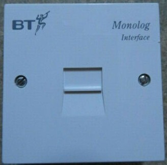
Monolog Interface Unit (MIU)
Originally known as the Long Line Extender, the Monolog Interface Unit (MIU) is wired in between the exchange equipment and the customer's line. It introduces a measure of current sensing to supplement line voltage sensing — addressing installation scenarios where voltage sensing alone is inadequate.
Why the MIU is Needed
In some circumstances, line voltage sensing alone is inadequate. Known trouble spots include:
| Exchange / Equipment | Problem |
|---|---|
| System X Mark 3 line cards | Line resistances higher than ~700 Ω make voltage sensing unreliable |
| UAX exchanges | Voltage sensing insufficient under certain line conditions |
| Certain UXD5 line cards | Only source 40 V off-load — insufficient for reliable voltage detection |
To avoid any possibility of errors, an MIU was used whenever a Monolog was connected within the exchange.
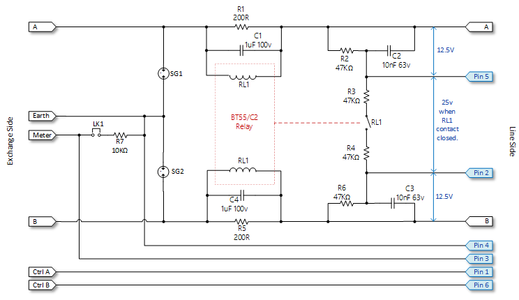
MIU Connections
| Terminal | Pins | Function |
|---|---|---|
| CTRL | 1, 6 | Control line input |
| LINE A, B | — | Line side — monitored line (customer side) |
| EQMT A, B | — | Exchange side — monitored line (equipment side) |
| METER | 3 | Meter pulses or external SPM pulses |
| EARTH | 4 | Earth reference input (also used with external SPM) |
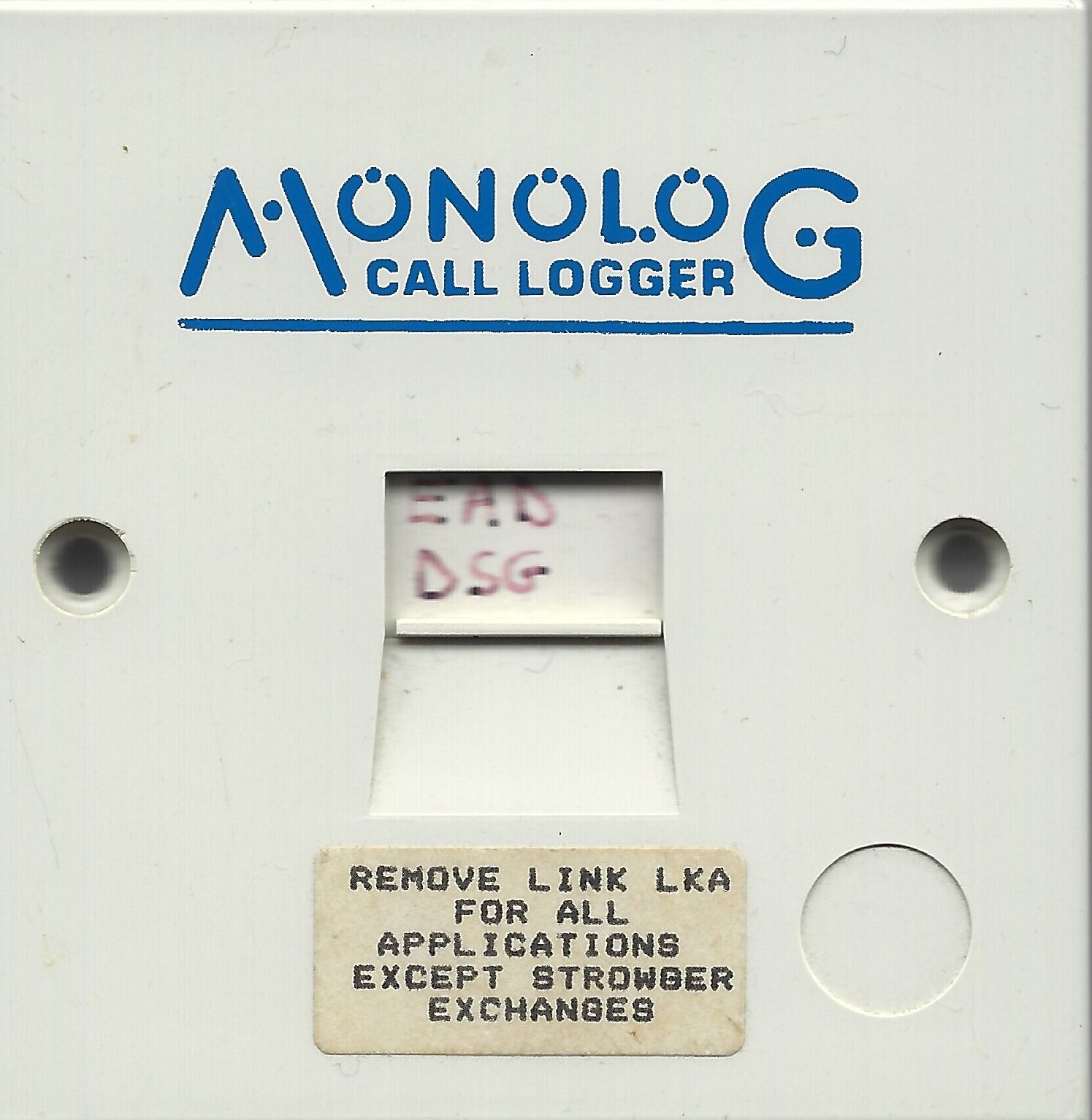
Meter Wire Link Option
The MIU provides a link option for a 10 kΩ pull-down resistor between the METER and EARTH wires:
| Exchange Type | Link Setting | Reason |
|---|---|---|
| Strowger | Link IN | Prevents the meter wire floating high during line idle conditions |
| TXE exchanges | Link OUT | Required — link must be removed |
Standard Secondary Socket (LJU)
In exceptional applications, a Monolog may be connected to a standard secondary Line Jack Unit (LJU). A Master socket must not be used under any circumstances other than as the master socket in a customer's own installation.
Monitor and control line inputs are not polarity conscious. All pin numbers refer to those printed on the terminals — pin 1 is at the retaining clip end of the socket.
| Pins | Function |
|---|---|
| 1, 6 | Control line input |
| 2, 5 | Monitor line input |
| 3 | Meter pulses or external SPM |
| 4 | Earth reference input (also used with external SPM) |
An additional 10 kΩ pull-down resistor is required between pins 3 and 4 in Strowger applications — see the MIU link option above.
If Monolog is plugged into a customer's line at their premises using the standard connecting cord, it will monitor that customer's line activity. However, the connecting cord does not allow the customer's line to be used as a control line.
Installation Locations
One of Monolog's key strengths was flexibility of deployment. It could be connected to a customer's line at virtually any accessible point between the exchange and the subscriber's premises — without any requirement for on-site configuration once in place.
| Location | Notes |
|---|---|
| Telephone exchange (MDF) | Most common deployment. Monolog connected via MIU at the Main Distribution Frame, with the control line brought in over the PSTN. |
| Primary Connection Point (PCP) | Street cabinet installation, typically using a D94471 cord either side of the MIU to connect to the jumper wires. Allowed monitoring without exchange access. |
| Subscriber's premises | Connected via standard secondary LJU or connecting cord. Note: the connecting cord does not allow the customer's line to serve as the control line. |
| Any intermediate point | In principle, Monolog could be deployed anywhere on the line between exchange and premises, provided suitable access and a control line were available. |
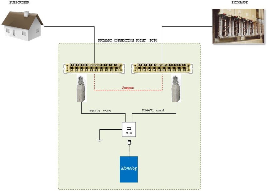
PCP Cabinet Installation
The diagram below illustrates a typical Primary Connection Point (PCP) deployment. The MIU is wired in between the two D94471 cords that replace the jumper between the subscriber and exchange sides of the PCP. The Monolog unit hangs below, powered and controlled via its PSTN control line.
Monolog to MIU Connection Lead
Monolog connects to the MIU via a short lead fitted with a 25-way male D-type connector at the Monolog end and a BT Plug 631A at the MIU end. The diagram below shows the pin and wire assignments for this lead.
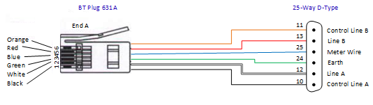
| 631A Pin | Wire Colour | D-Type Pin | Signal |
|---|---|---|---|
| 1 | Black | 10 | Control Line A |
| 2 | White | 12 | Line A |
| 3 | Green | 24 | Earth |
| 4 | Blue | 25 | Meter Wire |
| 5 | Red | 13 | Line B |
| 6 | Orange | 11 | Control Line B |
Line A/B and Control Line A/B inputs are not polarity conscious — the lead can be connected either way around on those pairs without affecting operation.
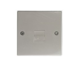
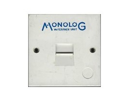
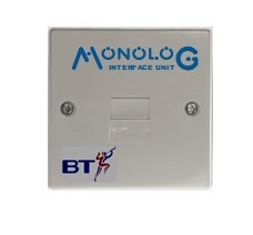
MIU Versions
Nine versions of the MIU were produced over its lifetime. Each can be identified by the cover legend and relay type. Known fault patterns and their remedies are listed below. Click any image to enlarge.