Meter Control Equipment (MCE)
To understand what Monolog was measuring, it helps to understand the exchange-side equipment that generated the meter pulses in the first place. The Meter Control Equipment (MCE) was the apparatus installed in British Telecom exchanges to provide Subscribers Private Meter (SPM) pulses — the 50 Hz longitudinal signals injected onto the subscriber's line at each chargeable unit boundary.
The loss of this facility — the phased withdrawal of the Meter Pulse Facility (MPF) between March 2007 and September 2008 — was the single most significant event in Monolog's obsolescence. Without MPF, independent metering verification was no longer possible.
How SPM Pulses Work
The need to indicate call cost at the subscriber's end of the line is achieved by routing the O/G A and B legs each through one winding of a three-winding injection transformer. When the exchange meter operates, a burst of 50 Hz is applied to the third winding. This produces an in-phase longitudinal signal at the subscriber's end, completed by earth return. If the circuit is correctly balanced, the pulse is inaudible to the subscriber.
Various types of detector register the transmitted pulse — including Subscribers Private Meters, private call logging equipment and PABXs. The MCE sends a standardised pulse: 43V, 50 Hz, 250 ± 50 ms duration — long enough to be reliably detected, short enough to be unambiguous.
SPM is induced longitudinally — the signal appears between the input and output connections of the SPM equipment, not across the A and B legs in the normal sense. This is why the SPM A and B legs are shorted together in certain Monolog connection diagrams, which can appear confusing at first glance.
Old Equipment — SPME
The earlier Subscribers Private Meter Equipment (SPME) used similar circuitry across TXS, TXK and TXE4 exchanges, varying only in mounting practice. In these systems the exchange meter pulse simply operated a relay to switch the 50 Hz signal to line. A known weakness was that any lengthening of the meter pulse — caused by other equipment in circuit — would be repeated onwards, making cost collection unreliable. The TXE2 SPME improved on this but did not send a standard-length pulse to line.
New MCE — Design Improvements
The new MCE was introduced to work reliably in any analogue exchange environment. Key improvements over the old SPME:
- Responds to positive, negative or ETH meter pulses from the exchange — not relay-switched
- Sends a standardised 43V 50 Hz pulse of 250 ± 50 ms to line regardless of input pulse shape
- Checks input pulse duration before responding — ignores transients and spurious signals
- Dedicated to one subscriber — fitted between the subscriber's line and the line circuit at the IDF/MDF via a jumper
- Metering signal registered by any BT-standard detector: SPM, private call loggers, PABXs
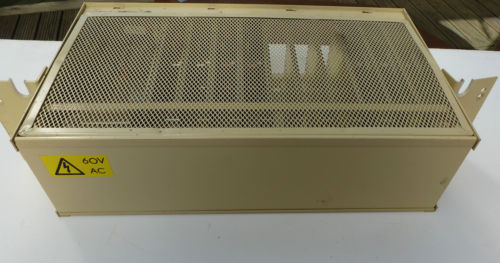
The MCE is powered from a dedicated 60V AC supply within the exchange rack — the same supply whose circuit documentation is available in the Downloads section.
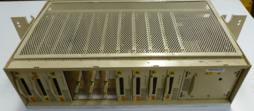
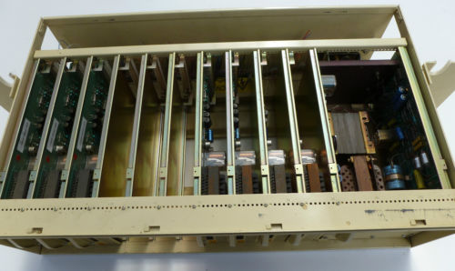
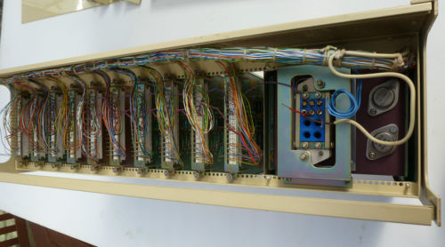
The MCE Rack
MCE cards were housed in a dedicated rack assembly. The rack accommodates multiple subscriber circuits, each on its own plug-in card, with a common services backplane providing the 60V AC metering supply and alarm functions. The rack is specified in BT Specification T80130.
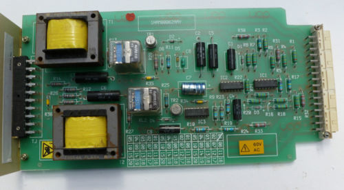
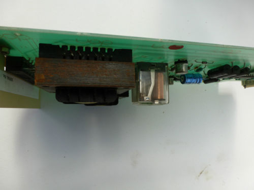
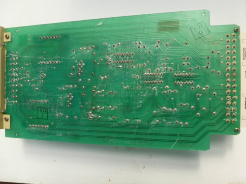
MCE Circuit Cards
Each plug-in card handles one subscriber circuit. The card carries the injection transformer (the large yellow toroidal components), the relay, rectifier and control circuitry. The underside shows the two-layer PCB track layout. Marked 60V AC, each card connects to the common 60V AC supply rail via the backplane.
Relationship to Monolog
Monolog's PULSES XSPM and PULSES SPM modes are specifically designed to detect the longitudinal 50 Hz pulses generated by MCE equipment. In the XSPM configuration, the SPM equipment is software-configured to the customer's number at the exchange but the SPM PLA is not connected to the customer's line — instead the pulses are fed directly to Monolog via the MIU METER terminal.
The Monolog firmware's A/D converter channels monitor the meter wire voltage, detecting the characteristic signature of each 50 Hz SPM pulse and incrementing the internal meter count accordingly. The MCE's standardised 250 ms pulse duration is long enough to be reliably captured by the Monolog sampling cycle.
Documentation
Original BT documentation for the MCE is available in the Downloads section, including the October 1983 technical description, shelf layout, rack common services specification (T80130) and the 60V AC SPM supply circuit. The British Telecom Metering System document is also available there — a broader overview of the whole charging and pulse generation system, from Clock 36 and the Multi-Phase Pulse Supply through to Local Call Timing and STD metering distribution.